Welcome to DC website!
 Tel:+86 21 62337776
  E-mailWelcome to DC website!
Tel:+86 21 62337776 E-mail
E-mailWelcome to DC website!
Tel:+86 21 62337776 E-mail| Home > Products > RFID & Others | Go back |
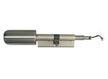
Rfid Lock Cylinder

Operating Manual for Intelligent Cylinders
*Thank you for choosing our product!
*Please read this manual carefully before using the product.
1.1 Product Configuration
SN | Auxiliary Products | Quantities |
1 | Intelligent Cylinder | 1 |
2 | Management Card | 1 |
3 | User Card | 2 |
4 | Mechanical Keys | 2 |
5 | Wrench | 1 |
6 | Instruction | 1 |
1.2 Product Parameters
SN | Name | Technical Parameters |
1 | Working Power Supply | High performance 3.6V Li-SoCL2 Battery (ER14250 1/2 AA size) |
2 | Battery Life | Maximum to 30000 door open operation, can operation another 100 times after the low voltage warning |
3 | Read Range | Less Classic Cards |
4 | Applicable Key Cards | MIFARE Classic Card |
5 | Support Customer Quantity | 63 |
6 | Working Temperature | -20 ~ +70℃ |
7 | Working Humidity | -20% ~ +97% R.H. |
8 | Cylinder Dimension | 60mm ~ 100mm |
9 | Handle Dimension | Inner handle 36.5mm(D) x 55mm(L) Outer handle 30mm(D) x 38mm(L) |
10 | Assembled Basis | DIN18252, EN1303 |
11 | Protection Grade | IP45 |
12 | Superficial Treatment | Stringy stainless steel |
1.3 Operating Instruction
1.3.1 Warning Tone Instructions (sound and light synchronizing indication )
SN | Function Name | Tone Description |
1 | Initial configuration of management card | di----da--- |
2 | Successful management card configuration | di--- |
3 | Failing management card configuration | di---di---da--- |
4 | Delete management card | di---di--- |
5 | Wake up operation | di---da--- |
6 | Management card punching | di---di---da---da--- |
7 | Add user cards | di--- |
8 | Delete user card | di---di--- |
9 | Successful door open | di----- |
10 | Failing door open | di---di---di---di----- |
11 | Low-voltage warming tone | di-----di----- |
Remarks: “---“means short sound, “-----“means long sound
1.3.2 Configure/Delete Management Card
Using the wrench which enclosed with the products to discharge the indoor knob, and press the rectangular button on the PCB (This button is put on the PCB of the indoor handle), then the sound “di---da---“is presented, that means you entry the configuration mode;
Punching initial management card, if the lock makes a sound “di---“, that means the card configuration is succeed.
Punching initial management card, if the lock makes a sound “di---di---da”, that means the card configuration is failure.
Punching configured management card, if the lock makes a sound “di---di”, that means the management card has deleted, and meantime, the user cards which configured by this management card have deleted.
1.3.3 Add/Delete User Card
Press the outside cylinder lightly in the direction of the door, the lock makes a sound “di---da---“that means the wake up is successful. The time for wake up is 8 seconds. all of the operations after this 8 seconds are invalid.
Punching the management card after the wake up operation, if cylinder makes a sound “di---di---da---da---“, please punching the unregistered user card, then if the unregistered user card, then if the cylinder make a sound “di---“ that means add the user card successful, and if the cylinder makes two sounds “di---di---“, that means delete the user card successful. (According to the outside lock core to punching the card)
1.3.4 Open/Lock Operation
Press the outside cylinder lightly in the direction of the door, the lock makes a sound “di---da---“that means the wake up is successful. The time for wake up is 8 seconds. All of the operations after this8 seconds are invalid.
Enter the wake up status after add the user card successfully, punching the card, if the warning tone is the long sound “di-----“that means the authentication is succeed, and the user can open the door or open the door, but if the warning tone is “di---di---di---di-----“that means the authentication is failure, the user can not open or lock the door.
If the key card is lost, the user can use the mechanical key to meet an emergency, please using the mechanical key insert the cylinder position, and turn the outside handle, then can open/lock the door.
1.3.5 Considerations
The management card is just used for configuring the user card, which cannot open the lock.
Every lock has one piece of the management card at most, if reconfigure the management card, all of the user card will be delete.
If the management card is lost, please contact with the manufacturer to purchase the new initial management card and configure again.
The time for wake up is 8 seconds. All of the operations after this 8 seconds are invalid, the customer need to wake up again and then continue to opening door or operating card management.
The time for door lock and door open is 8 seconds. The system will entry the sleeping mode after this 8 seconds.
If you hear the “di-----di-----“ two long sounds after the wake up operation, that means low-voltage warning, please replace the battery in time for this moment the lock only can opening the door 100 times.
1.4 Cylinder Installation Instructions
(1) Cylinder Components and Related Tools Introduction

(2) Assembly Sequence
1、The Outside Cylinder components
Please disassembly the cylinder components in following order Knob Cap ⑤, Antenna Cover ④. Rotary Buckle ③, Clamp Ring ② and Inner Assembly ①.
Note: please be caution to take down the data wire which connects inner assembly and antenna cover.

2、Locating Intelligent Cylinder
Insert the cylinder inner assembly① into the lock hole, (the antenna cover on the outside of the door). Adjust the cylinder positions to make the lock core positioning screw snap to the center of the lock hole, and inserting the cylinder setscrew⑦ into lock hole, then screw down it with the cylinder position screw hole.
3、Clamp Ring and Rotary Buckle Installation
Put clamp ring② and rotary buckle③ into cylinder center axis one by one. Make the direction of the lock core gap surface compliance with the with the inside gap surface of the rotary buckle③, and then use the buckle screw③, and then use the buckle screw⑥ to fix it.
4、Antenna Cover Connection
Insert the data wire cable into antenna cover connector.
5、Antenna Cover Block Out
Put the antenna cover④ into the rotary buckle③ annular groove, and make the antenna cover④ circumferential notch to link with the buckle screw⑥. Please notice to avoid the data wire blocking the antenna cover when installed.
6、The Knob Cap Installation
Using the wrench⑧ which enclosed with the product to install the knob cap⑤ into the clamp ring② thread.
1.5 Routing Maintenance and Treatment
1、 Protect the cylinder from touching with corrosive substances to avoid locking surface coat. And reduce the locking surface glossiness.
2、 Handles and knobs have a direct impact on the flexibility of the lock for they are the key parts for the door, please do not hang anything on them.
3、 Please replace the new battery in time when the battery is weak.
4、 Please keep the mechanical keys well properly against unexpected need.
If you have any questions, please contact us and we will do our best to serve you in 7*24 hours